The QMX+ is an awesome little radio. Inexpensive, compact, solid radio. What it needs is battery and a speaker.
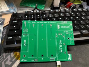
There are 2 options out there and I went the easiest from my limited solder abilities. TA7MNA designed an easy board that I ordered from JPCBL in China and took about a week. Minimum order is 5 and with shipping it comes out to arround $11.00 a board. The PCB is very high quality. For my first PCB order I was suprised at how perfect it all came out.
Now gather your parts to build the board. I shop on amazon, milege may vary.
- 3x 1×18650 Li-ion Batteries: I used 2900mAh INR18650 cells. There must be three 1×18650 battery holders.
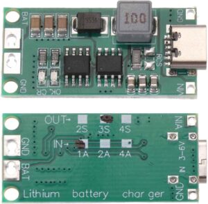
- 3S 1A Multi Cell Charger Board (DDTCCRUB): I used 1A and 2A versions. 3A might be a problem due to heating.
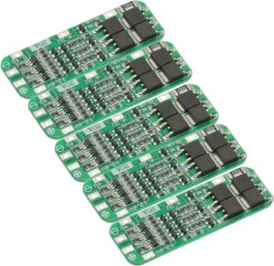
- 1x 3S 20A BMS Board
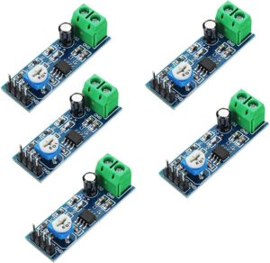
- 1x LM386 Audio Amplifier Breakout Board: You have to desolder the pins.
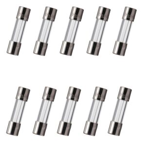
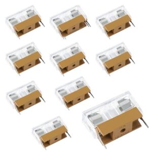
- 1x 5x20mm 3A Fuse: For further protection.
- 1x 5x20mm Fuse Holder: Compatible with most 2 pin 5x20mm fuse holders. It must have 22.86mm (0.9in) or 15.24mm (0.6in) pin pitch.
- 2x 1K 1/4W THT or 0805 SMD Resistors: Solder as you like SMD or THT.
- 8 Ohm Speaker: Necessary for audio output. Use the screw terminals on the audio amplifier board. Small laptop speakers should work.
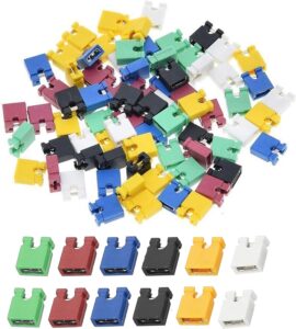
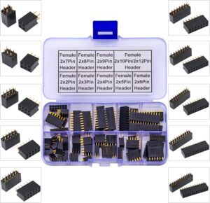
- 1x 2×3, 1x 2×2, 1x 1×5 2.54mm Female and Male Pin Headers: To mount the PCB directly on the main board.
| Item # | *Qty | Cost | Total | Manufacturer | *Mfg Part # | Description / Value |
| 1 | 3 | $6.00 | $18.00 | TEKOWEE | INR18650 | 18650 Li-ion Battery |
| 2 | 1 | $8.31 | $8.31 | DDTCCRUB | 3S-2A | Battery Charging Module Step Up Boost |
| 3 | 4 | $0.03 | $0.12 | Bnnrjia | 4 Nylon M3 Screws, Nuts | |
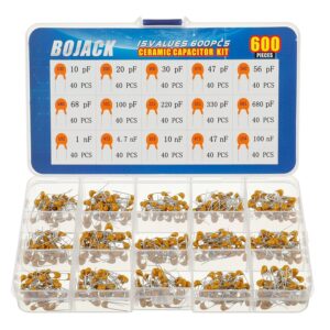
| 4 | 1 | $0.02 | $0.02 | BOJACK | 104 100np | Ceramic Capacitor |
| 5 | 1 | $2.00 | $2.00 | Speaker | Speaker 8ohm | |
| 6 | 1 | $1.09 | $1.09 | GODITMODULES | 3S BMS 20A Li-ion Lithium Battery 18650 BMS Charger | |
| 7 | 2 | $0.03 | $0.06 | California Resistor | 1K 1/4W THT or 0805 SMD Resistors | |
| 8 | 1 | $1.50 | $1.50 | ANY | LM386 | LM3806 Amplifier Board |
| 9 | 1 | $0.65 | $0.65 | ANY | 5X20MM 10AMP Fuse | 5X20MM 10AMP Fuse |
| 10 | 3 | $0.75 | $2.25 | RHCXCYTJ | 18650 Battery Holder (Single, Solder) | |
| 11 | 1 | $0.60 | $0.60 | BOJACK | 3A FUSE | |
| 12 | 1 | $0.04 | $0.04 | 2×3 Header Female | ||
| 13 | 1 | $0.04 | $0.04 | 2×2 Header Female | ||
| 1 | $0.04 | $0.04 | 1×5 Header Female | |||
| 14 | 23 | $0.01 | $0.23 | Male Pins (different amounts, 1 5 pin, 2×2, 2×3, single pins) | ||
| Subtotal | $34.95 | |||||
| CUSTOM | ||||||
| Item # | *Qty | Cost | Total | Manufacturer | *Mfg Part # | Description / Value |
| 1 | 1 | $11.00 | $11.00 | JCB | Custom PCB | |
| Total BOM Build Price: | $45.95 | |||||
Gotchas are make sure you get the single battery holder and not the 3 in one or it wont fit. Fuse holder has to have the little posts. I knew this from watching youtube videos, but I can see how some would make the mistake and end up ordering again.
The Audio LM386 board will need the pins moved to the bottom vs the top, simple solder heat up and push them through worked for me.
- Solder the female headers to the bottom first. These will connect the board to the main traciver board.
- Solder all the sigle pins to the board before the little boards are attached. its just easier. Solder the Battery, and the fuse in place. Leave fuse out for now.
- Solder the 12v jumper pins next to the fuse. You will need a jumper, some old stuff still has them in side in a pinch.
- Solder on the R3 and R4 Resistors (1K 1/4W)
- Solder the Ceramic Capacitor (104 100np)
- Now you can solder the boards on.
- If the pins dont line up, make sure you have the exact boards in the BOM list.
- Once all the boards are in place, you can pull the main board from the radio to add pins to connect the battery board.
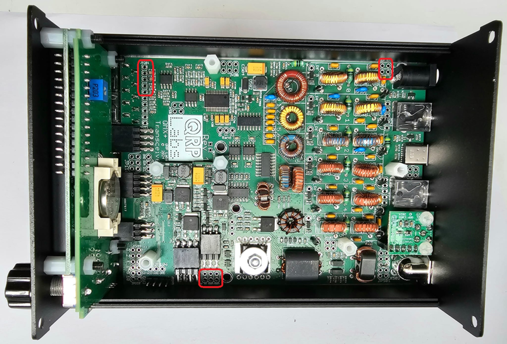
Add 5 pins to the top Left of this image, then 2×2 top right and 2×3 on the bottom. Make sure none of the pins protrude to for as it will contact the bottom of the case. Make sure the solder spots and clean with no shorts because you will be working near the DC input.
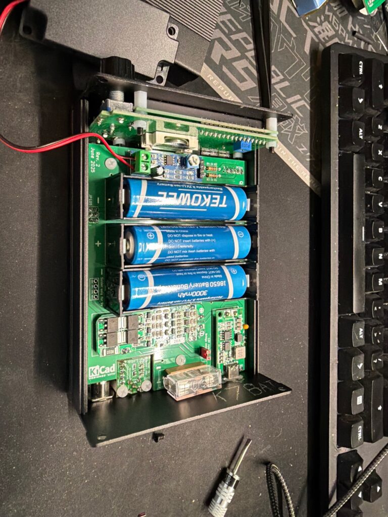
Now you will want to add the spacers (2) if you have them and the M3 nylon screws. I glued 3 nuts together to make my standoffs becasue I was cheap. Then I screwed it all togther. Each step I tested to make sure nothing was going to short.
Then I add the 12V jumper seen in red, and the fuse.
At this point you can start to reassemble the radio to test it. I recommend adding the speaker too if you want one in the case. If not there is the headphone jack on the out side.
Test and make sure everything is working. You should be able to power up and adjust your volume using a small screwdriver.
I am adding all the amazon part images I bought just incase you need help finding the part or matching it up.
I will clean up this how to soon, just wanted to get my thoughts down.